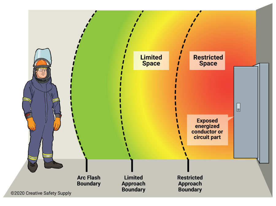
An arc flash boundary is the distance from the equipment in question to the point where the energy that would be present in an arc flash is 1.2 cal/cm2. This is the level at which it will cause only second-degree burns rather than third-degree. Calculating where the boundary will be in any given situation is something that should be done by an electrical engineer. When they are performing this task, here are the things that they will need to do.
How to Calculate the Arc Flash Boundary
Calculating an arc flash boundary is going to be based on the voltage of the equipment that would cause the arc flash. The exact method of calculation is different for AC and DC systems as well, so it is critical to have this information available.

Most companies will use software programs where they can enter in the voltage information about a piece of equipment, and it will calculate the arc flash boundary automatically. This will provide accurate information that can be used to set the distances in your facility.
Calculate your minimum approach distance (MADs)
The min. approach distances calculator for energized equipment makes it easy.
If your business doesn’t have this software, or wants to double check the results manually, there are two main methods of calculating the boundary. Looking each one up will provide you with the exact calculations needed to get the distances. The options are:
- NFPA 70E – NFPA 70E offers a formula for calculating the incident energy of a machine.
- IEEE 1584 – This option uses an empirically-based formula that uses lab-tested information, and is typically seen as more accurate than the NFPA option.
Regardless of what method you choose, or even if you use the software, you must be absolutely certain that you have the voltages correct. If you enter this information in incorrectly, the arc flash boundary that is measured will be incorrect, and employees and the entire facility will be at greater danger.
Additional Arc Flash facts:
- The arc flash boundary is based on the incident energy level of 1.2 cal/cm², which is the threshold for the onset of a second-degree burn. Source: https://www.safeopedia.com/definition/6807/arc-flash-boundary
- The arc flash boundary can vary depending on the type, size, and configuration of the electrical equipment, as well as the available fault current and the clearing time of the protective devices. Source: https://bing.com/search?q=arc+flash+boundary+facts
- The arc flash boundary can be reduced by using devices that limit the fault current or clear the fault faster, such as current-limiting fuses, fast-acting circuit breakers, or arc flash relays. Source: https://www.fluke.com/en-us/learn/blog/safety/understanding-arc-flash-boundary
- The arc flash boundary can also be affected by environmental factors, such as humidity, temperature, and altitude, which can influence the arc flash duration and intensity. Source: https://www.electricityforum.com/iep/arc-flash/arc-flash-boundary-chart
- The arc flash boundary should be clearly marked with signs, labels, or barricades to warn workers of the potential hazard and the required PPE. Source: https://www.electricityforum.com/iep/arc-flash-electrical-safety/arc-flash-vs-arc-blast
- The arc flash boundary should be recalculated whenever there are changes in the electrical system, such as new equipment, modifications, or maintenance. Source: https://www.electricityforum.com/iep/arc-flash-electrical-safety/arc-flash-boundary
Similar Questions
- What is an arc flash boundary?
- How can I mark off arc flash boundaries?
- How do I complete an arc flash hazard analysis?
- At what voltage can an arc flash occur?
- Are arc flash labels required?
- What is an arc flash?
- How do I prevent an arc flash from happening?
- What are different ratings of arc flash PPE?
- What organizations enforce arc flash standards?


